- Support for 12 V and 24 V input lighting
- Support for Mitsubishi Electric iQSS
- Recognition of individual lighting and monitoring/feedback by the new technology FALUX sensing +
Various types of lighting can be connected, allowing for unification of controllers
The OPPX Series supports both 12 V and 24 V input lighting, and also allows connecting other companies’ LED lighting units. This enables controller unification even when using multiple types of lighting units, such as general-purpose lighting and line lighting. And since communication standard unification is also possible, wiring reduction is achieved. In the case of OPPX-1601224P4/E4, both 12 and 24 VDC input lighting units can be connected using a single power supply unit.

All models in the OPPX Series support PWM intensity control used for general-purpose lighting units and voltage intensity control suitable for line lighting units.
They also support strobe overdrive that enables high-brightness lighting, so a single unit can handle various inspection applications.
Single-channel light intensity control products have been the mainstream for voltage intensity control power supplies used for line lighting unit.
Even if multiple lighting units were connected, the light intensity value and illumination timing could not be controlled separately.
The OPPX Series allows setting the light intensity value and illumination timing for each lighting unit, enabling control with a single controller (maximum capacity: 200 W) even when using lighting units in multiple inspection processes.
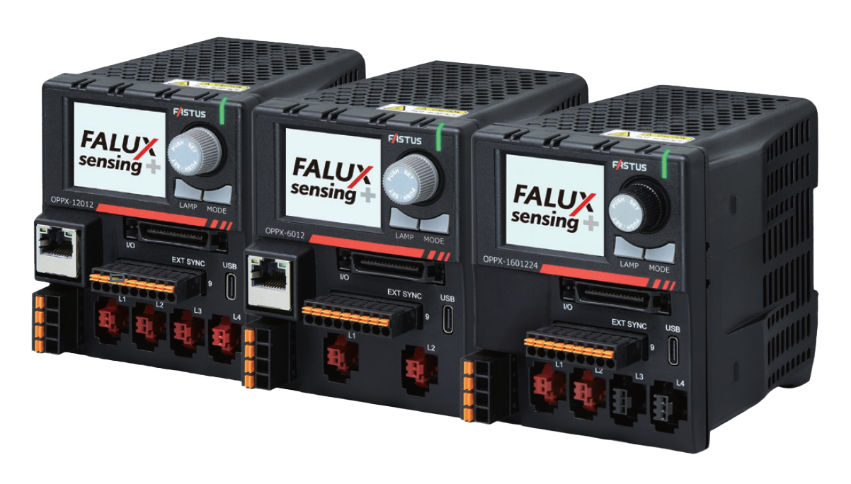
Compact case with easy-to-read LCD and fully functional controler panel
High capacity in a compact size is achieved through high-density mounting technology and optimal heat dissipation design.
Since its height is equivalent to that of the majority of PLCs (100 mm), it can be easily installed inside a panel.


Monitoring
The photodiode inside the lighting unit receives the light from the lighting unit itself and displays the brightness and temperature as the monitor value on the controller.
Viewable items
- Light intensity value
- Monitor value (Brightness)
- LAMP intensity
- Correction value
- Temperature
- Internal temperature
- Model name
- Serial number
- Total illumination time
| Model | Capacity | Output voltage | Ethernet | No. of channels |
|---|---|---|---|---|
| OPPX-6012P2 | 60 W (30 W/channel) | 12 V | ― | 2 |
| OPPX-6012E2 | ✓ | 2 | ||
| OPPX-12012P4 | 120 W (30 W/channel) | ― | 4 | |
| OPPX-12012E4 | ✓ | 4 |
| Model | Capacity | Output voltage | Ethernet | No. of channels |
|---|---|---|---|---|
| OPPX-10024P2 | 100 W (50 W/channel) | 24 V | ― | 2 |
| OPPX-10024E2 | ✓ | 2 | ||
| OPPX-20024P4 | 200 W (50 W/channel) | ― | 4 | |
| OPPX-20024E4 | ✓ | 4 |
| Model | Capacity | Output voltage | Ethernet | No. of channels |
|---|---|---|---|---|
| OPPX-1601224P4 | 160 W (12 V: 30 W × 2 channels, 24 V: 50 W × 2 channels) |
12 V / 24 V | ― | 4 |
| OPPX-1601224E4 | ✓ | 4 |
| Model | Without Ethernet | OPPX-6012P2 | OPPX-12012P4 | OPPX-1601224P4 | OPPX-10024P2 | OPPX-20024P4 | ||
|---|---|---|---|---|---|---|---|---|
| With Ethernet | OPPX-6012E2 | OPPX-12012E4 | OPPX-1601224E4 | OPPX-10024E2 | OPPX-20024E4 | |||
| Supply voltage | 24 VDC ±10% | |||||||
| Output channels | 2 ch | 4 ch | 2 ch (L1, L2) |
2 ch (L3, L4) |
2 ch | 4 ch | ||
| Connectable illumination ratings |
All channels max. | 60 W | 120 W | 60 W | 100 W | 100 W | 200 W | |
| Max. per channel | 30 W/ch | 50 W/ch | ||||||
| Lighting output voltage |
PWM mode | 12 VDC (standard) | 24 VDC (standard) | |||||
| STB mode*1 | 18 VDC | 48 VDC | ||||||
| DC mode | 8 to 12 VDC | Low: 12 to 24 V, High: 18 to 24 V | ||||||
| L-INT mode | 12 VDC | 24 VDC | ||||||
| L-INT STB mode*1 | 18 VDC | 36 VDC | ||||||
| Lighting output current |
PWM / DC / L-INT mode | 2.5 A/ch | 2.0 A/ch | |||||
| STB / L-INT STB mode | 8.0 A/ch (duty 10%) | 5.0 A/ch (duty 7%) | ||||||
| Light intensity | PWM intensity control, Frequency: 50 kHz, 100 kHz, 130 kHz Voltage variable mode |
PWM intensity control, Frequency: 100 kHz, 130 kHz Voltage variable mode |
||||||
| Strobe | Illumination time*1 | When PWM frequency 50 kHz is set: 20 μs to 19980 μs (in 20 μs steps), 1 ms to 999 ms (1 ms steps) When PWM frequency 100 kHz and 100 kHz DC are set: 10 μs to 9990 μs (in 10 μs steps), 1 ms to 999 ms (1 ms steps) When PWM frequency 130 kHz DC is set: 7.7 μs to 7684.6 μs (in 7.7 μs steps), 1 ms to 999 ms (in 1 ms steps) *When 1 ms is exceeded: Driven at 12 VDC for 12 V type, and 24 VDC for 24 V type |
||||||
| Flash cycle limit | 10% Duty (10 times or more than the required pulse width cycle) |
7% Duty (14.3 times or more than the required pulse width cycle) |
||||||
| Input | External synchronization control pin (SYNC1 to 4, SEQRST) |
When 5 V SYNC is OFF |
ON voltage: 12 to 24 V, OFF voltage: 1 V or less NPN Response time: OFF → ON within 2 μs, ON → OFF within 10 μs PNP Response time: OFF → ON within 2 μs, ON → OFF within 12 μs |
|||||
| When 5 V SYNC is ON |
ON voltage: 5 to 24 V, OFF voltage: 1 V or less |
|||||||
| External parallel control pin | Please refer to the user's manual. | |||||||
| Output | Multi-function outputs with customizable content: 6 points Photocoupler open collector output Max. 50 mA / 30 VDC, residual voltage 1.5 V (when 10 mA) |
|||||||
| Communication interfaces |
USB (Full-speed, Type-C connector) |
Serial communication by virtual COM port | ||||||
| RS-232C | 4800/9600/19200/38400/57600/115200 bps | |||||||
| Ethernet (10BASE-T/100BASE-TX) *Only installed in OPPX-□□□□E□ |
UDP, TCP, DHCP, and iQSS (Mitsubishi Electric iQ Sensor Solution) | |||||||
| Ambient temperature/humidity | 0 to 40°C / 20 to 85% RH (no condensation) | |||||||
| Storage temperature/humidity | -20 to 70°C / 20 to 95% RH (no condensation) | |||||||
| Vibration resistance | 10 to 55 Hz, double amplitude 1.5 mm; 2 hours in each of the X, Y, and Z directions | |||||||
| Shock resistance | Approx. 10 G, 3 times in each of the X, Y, and Z directions | |||||||
| Material | Polycarbonate | |||||||
| Weight | 2 ch type: 260 g, 4 ch type: 360 g | |||||||
| Degree of protection | IP20 (IEC 60529) | |||||||
| Applicable regulations |
EMC*2 | EU EMC directive (2014/30/EU) UK directive EMC (The Electromagnetic Compatibility Regulations 2016) |
||||||
| Environment |
EU RoHS directive (2011/65/EU), China RoHS (MIIT Order No.32) |
|||||||
| Applicable standards | EN IEC 61326-1 (Group 1, Class A according to EN 55011) | |||||||
| Design life | 7 years (maximum load, 24 hours continuous use, 40°C environment) | |||||||
| Accessories | External illumination control connector, power connector, instruction manual | |||||||